niedziela, 26 października 2014

Second launch with new payload


Our project has a new payload - redesigned APRS tracker and a VHF/UHF voice repeater.

APRS tracker is made of Arduino Nano, and G-Space Bluetooth GPS receiver - with RS232 data bus taken from the mainboard. Arduino Nano is powered using internal GPS receiver battery (3.7 V) upconverted to the 5V. We are using awesome QAPRS library (https://bitbucket.org/Qyon/arduinoqaprs/downloads) to generate the modulated audio signal and pass it to the VHF transmitter.
APRS tracker internals

APRS tracker mounted to the back of a VHF radio

Another part of the payload if a VHF/UHF radio repeater. We started to build our own but a more effective  solution (resulting in lighter payload) was to use a repeater build into a Wouxun KG-UV8D dual-band, handheld radio.

Don't worry - this line only looks like it is loosely attached to the radio :)

Here is both tracker and repeater connected to the kite:


Due to a weak wind we were able to lift the payload only 73 meters above the ground. APRS direct radio path was 59 kilometers. Wouxun UV8D was set up to work as a two-way dual band repeater  on 145,500/438,500 MHz frequency pair. Kite operators were calling on a 438,500 MHz frequency. Launch site was about 80 km from Warsaw (Poland) and unfortunately our friends in Warsaw that were monitoring 145,500 MHz frequency weren't able to get a usable signal.

All transmitter were using 5W of power each. Unfortunately this time we were forced to use lower quality antennas (all-use uhf/vhf vendor supplied) which resulted in weaker coverage. We confirmed that all parts of a set-up: kite, line winder, APRS tracker and voice repeater work fine and their weight is low enough to be lift up during moderate wind conditions.

Next goal: to lift payload 250 meters above ground and establish reliable voice connection. We also plan to achieve direct path APRS data transmission of 150 km.

wtorek, 14 stycznia 2014

Elegant solution for carrier detect in Wouxun/Baofeng radios

Building small and light repeater, I came across a problem of getting carrier detect signal from a Baofeng BF-888 radio. I like this radio so I didn't want to drill any holes in it for additional wire.

Looking at a pinout of plug used for external speaker and programming I found one unused pin - tip of the 3,5mm jack. For unknown reason there is a 3V voltage on this pin and you can draw up to 50mA from it.
Probably some more expensive external microphones use it for their amplifiers.

This voltage is also present on a Wouxun KG-UVD1 radio I own (looking at the service manual you can see circuit providing it). This is probably some kind of standard for Kenwood  type connector used in most cheap Chinese radios. This is even referenced by some companies selling those:


Anyway -  when receiving a transmission, you don't need a microphone amplifier, right? :). So my idea was to ground this pin every time radio opens its squelch.

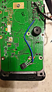
When it comes to BF-888, to get carrier detection status you need to use one of the IC pins from the back of a PCB. Unfortunately, connector socket pins are from the front side of a board. I didn't want to drill a hole in a PCB to lead a wire between its sides, so using a multimeter I found a solution :). One of the pins visible at the bottom of a board (the one with resistor soldered by me) is used to power an audio amplifier.
To conserve power, amplifier is powered up only when radio receives a transmission and opens its quelch (CTCSS and DCS settings are of course validated before).

My circuitry is trivial - using 5kOhm resistor, power from audio amplifier enables BC547 transistor and grounds tip of the radio connector - voltage on the connector drops from 3V to 0V. Squelch closes, radio disables audio amplifier and shuts down transistor. Voila :)

This technique has one drawback - radio enables audio amplifier also when generates sounds by itself - beeping when battery is low, etc. You need to be aware of it - if this is a problem for you, consider disabling internal sounds when programming your radio. Or drill a small hole in a PCB and get real carrier detect signal from the back side.

Have fun.

BF-888 radio carrier detect circuitry


środa, 9 października 2013

Motor speed controller is ready


I've finally finished my electrical motor speed controller box to use with line winder. It is based on a chinese PWM controller bought for about 12$ on aliexpress.com. It can deliver up to 15A with voltage range of 12-30V.

I've added voltage meter, amp meter and a rotary switch. Switch is used along with electrical relay to connect and disconnect PWM controller to the motor. In the future I'll add additional PWM controller and some artificial resistance load to create electrodynamic motor brake to control speed at which the line will be unwound (usefull especially with high wind speeds). What is really neat,   when potentiometer is set to "0" PWM controller shorts both motor wires together -  force needed then to rotate the engine manually is so big it prevents line from unwinding when pulled by kite.

Electrical relay switch coil circuit is rated for 12V so I added additional resistors  to prevent it from damaging when 24V is applied.


środa, 4 września 2013

First tests of the kite line winder

Kite line winder prototype using 24V 250W electric motor (12V supplied during test) - full success :). About 3-4A of current drawn when pulling kite at moderate wind. Next priority is  PWM speed controller and a fancy switch and cable box. Winder weights about 7 kg  and was designed to fit into standard car trunk, although next version will be much smaller - as you can see there is a lot of free space on the frame.
I got inspiration from http://beachwinches.com page - a lot of great DIY winch designs.


poniedziałek, 29 lipca 2013

Kite lifted transmitter - experiment 1


Purpose of the first experiment was to test my new kite - HQ PowerSled 36 and its lifting capabilities. Smaller kites (like PowerSled 14) give too small pull to lift even 500g payload at moderate winds.
Final goal is to have platform that allows lifting a 1000g payload in winds at 10 km/h or greater.

Payload: custom made APRS tracker (based on Arduino Nano) with 5W Wouxun KG-UVD1P transmitter and GPS receiver. Antena was simple 144 MHz quarter-wave, unfortunately - bent 90 degree during experiment. Payload weight: about 600g.

Custom-made APRS tracker

Wind speed: 25 km/h - according to the Warsaw-Okęcie (EPWA) airport weather service.

Max altitude: 160 m above ground level (measurement based on GPS record). About 250m of kite line was used.

Altitude graph

Longest RF signal path (based on http://aprs.fi measurment): 106 km

http://aprs.fi/info/a/SQ5OMQ-1


2013-07-13 17:17:26 CEST: SQ5OMQ-1>BEACON,WIDE1-1,qAR,SR5DRK:!5211.11N/02122.09E-TRACKER NA LATAWCU
2013-07-13 17:17:58 CEST: SQ5OMQ-1>BEACON,WIDE1-1,qAR,SR5DRK:$GPGGA,151724.000,5211.1068,N,02122.0938,E,1,07,1.1,227.4,M,38.8,M,,0000*56

SR5DRK station received over 14 consecutive APRS frames, so the RF path can be considered stable.

Experiment notes: At 25 km/h wind, PowerSled 36 gives so strong pull that it's very difficult  for 2 persons to get it back on ground. Heavy, electric engine powered line winder is needed for further experiments. Construction of such winder is under way.

Goal for the next experiment: Tests of the winder, reaching altitude of 300m above ground level. Different mount of the radio antenna to get better efficiency.


Misc:


HQ PowerSled 36


Kite and transmitter in the air